Requirement
Intersite traffic between Site10 and Site20 must pass the firewall at Site50.
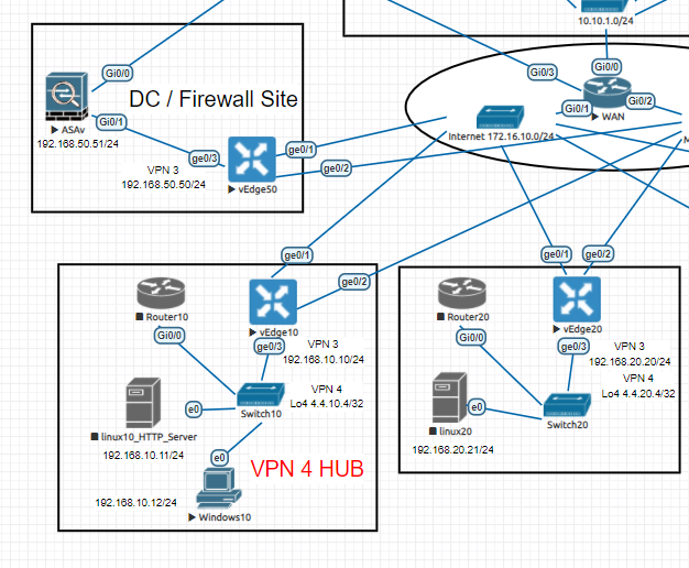
Topology

Implementation
Again the more hands on you get with Policy, they soon become logical and straightforward. Leaning on the previous post on Service Chaining we have the following steps to deal with this scenario.
Advertise a Service VPN from Site50

Create Control Policy to match the traffic / send to the service
I did this via the Policy GUI, again it’s quite straightforward to out together. We need to match on Site20, set the action to use the FW service and apply to Site10.

How does this look on vSmart when applied to Site10 in an outbound direction?
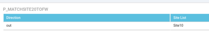

Notice how the policy works, it’s quite logical and intuitive to follow. Basically match Site20, for any prefix, accept it and send to the FW service. Oh and accept everything else of course.
Verify
Ok this was quite an interesting exercise.. Let’s start basic and ping from Site10 to Site 20:

Ok so that works.. but how do we know it is hitting the firewall? Well there are a few things we can check, let’s look at the firewall 1st. I’m expecting traffic to arrive on the inside interface 192.168.50.51/24 and then route back to vEdge50 -> vEdge20.
Setting up the ASAv in EVE-NG was actually really easy to do, but there is one trick you need to remember for traffic to be permitted between 2 hosts on the same interface:

So let’s check the firewall and see if it can see the traffic in the log:

So how does this work from a routing perspective? Let’s check the routes in VPN3 for Site20:

As per the screencap, routes to 192.168.20.0/24 have a TLOC of 7.7.7.50, which is of course Site 50! So that it is how it works! 🙂 Very clever, but logical to understand.
What else can we check? What about a traceroute from Site10 to Site20?

So we can see the vEdge50 hop, but interestingly enough the 3rd hop is also the .50 host not the .51 host. I would expect to see the firewall if I’m honest, but I’m not sure on this.. possibly how service chaining behaves within the same VPN?
Anyway I am happy that we have delivered the requirement for this VPN3 site to site traffic to route via the single node service chain. (Also in VPN3) Remember that as per Cisco docimentation, you can do this between different VPNs as per example topology:

So now we have Site 1 and Site 2 – VPN 20 and VPN 30, with the firewall in VPN10. and a 2nd service in VPN10. Therefore more ‘route leaking’ between VPNs. (or VRFs!) The building blocks for this are documented on my previous post, so I will not cover this in the lab. The concepts are similar but this time you need to apply to Site 1 and also the vEdge Hub-1 site, as this has to also make sure traffic flows to the 2nd service behind vEdge Hub-2.

You must be logged in to post a comment.